Nuke is great, but it doesn’t always have what you want. For those coming from After Effects to Nuke, this is one of the tools you may be missing, the Beam. Simply specify a start and end position, animate the time and watch it shoot across your screen. The handy benefit of it over say, a roto paint, is that it can easily fake 3D movement at the press of a button. I made the tool to have the exact same settings as the AE version, so hopefully there should be no confusion.
Installing
Download from here.
To run, simply drop a Blink Script node in Nuke, navigate to where you placed the downloaded script, and then hit Load. In Kernel Parameters you can change the settings, or even publish the node into a gizmo. For the unfamiliar, you can’t simply copy and paste a Blink Script node from one computer to another. Each user will need to load the script themselves unless you convert it into a gizmo.
Code Breakdown
For those unfamiliar with blink script, I give a quick and basic intro over here. I’ll assume you are familiar with the param, local and define() sections of the script, and move onto the actual workings of the script. Firstly, the init() function, where we set up the local variables that won’t change based on position:
// Basic initialisation
direction = end - start;
full_length = length( start - end );
min_width = min( start_width, end_width );
max_width = max( start_width, end_width );

if ( direction.y == 0 )
  horizontal = true;
else if ( direction.x == 0 )
  vertical = true;
else {
  vertical = false;
  horizontal = false;
  slope = direction.y / direction.x;
  y_intercept = end.y - slope * end.x;
  slope_perp = -( 1 / slope );
}
The easy stuff. We get the direction specified by the target markers, and store the min and max width as this will help us calculate the 3d perspective later. We’ll be using line expressions to calculate our beam, but the slope of a line ranges from 0 at horizontal to infinity at vertical, which will break our script. So, we do a quick check to avoid this and prepare the slope if needed.
// ---------- Beam location ----------

// Fit time to allow for length to disappear from both ends
float current_length = ( full_length * len ) / full_length;
float range = clamp( start_time, 0.0f, 1.0f) * ( 1 + current_length );
float start_dist = clamp( range - current_length, 0.0f, 1.0f );
float end_dist = clamp( range, 0.0f, 1.0f );

if ( persp ) {
  start_dist = linear_to_perspective( start_dist );
  end_dist = linear_to_perspective( end_dist );
}

anim_start = start + direction * start_dist;
anim_end = start + direction * end_dist;
Next up, we want the user to control the length of the beam, and for it to appear from the start point and disappear from the end. To do this, we’ll animate a new start and end point that stay a length apart, and fit the range of movement to extend the length off both ends. Seeing as we don’t want the beam to actually appear from further out, we clamp it between the 0 to 1 range. This diagram might clear it up a little:

This is straightforward for the 2D view, but what if we want the 3D perspective? There’s a quick way to convert a normalised number from linear to perspective, and because we’re converting the start and end positions, we’ll automatically get the correct length adjustment along with the timing.
Now, for the linear to perspective conversion, I tried a number of methods, mostly quadratic and cubic equations, but nothing was quite matching the correct movement. I’m certain there’s a simpler equation than what I’ve done, and if you know it then please do let me know! However, I instead did a lot of math, and worked out that the following function will always work.
int depth = -1;
float last_low = 0.0f;
float last_high = 1.0f;
float tolerance = 0.00001f;
float distance_to_high = fabs( last_high - linear );
float distance_to_low = fabs( last_low - linear );

// Find the amount of times to halve 1 to get to time
while ( distance_to_high > tolerance && distance_to_low > tolerance) {
  depth++;
  float difference = ( last_high - last_low ) / 2.0f;
  if ( distance_to_high < distance_to_low )
    last_low += difference;
  else
    last_high -= difference;
  distance_to_high = fabs( last_high - linear );
  distance_to_low = fabs( last_low - linear );
}
This looks messy, but all we’re doing is finding the number of times we need to halve between and 0 and 1 to get to our current linear number. To get this exact may take a while, so we implement a tolerance value that we stop when we’re that close. All we’re interested in is this depth number.
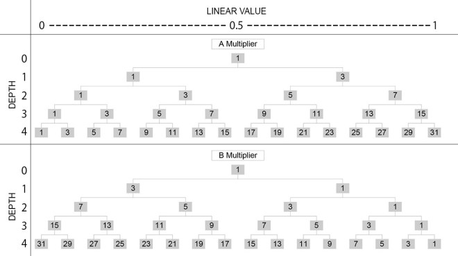
// Calculate the multiplier values for the trapezoid midpoint equation
float options = pow( 2, depth );
float factor = options * linear;

float min_mult = factor * 2;
float max_mult = ( options - factor ) * 2;

// Calculate perspective using midpoint equation with multipliers
float perspective;
if ( start_width < end_width )
  perspective = ( ( min_mult * min_width * full_length ) / ( min_mult * min_width + max_mult * max_width ) / full_length );
else
  perspective = 1 - ( ( max_mult * min_width * full_length ) / ( max_mult * min_width + min_mult * max_width ) / full_length );

return perspective;
Ok, this is actually a bit messy. There’s an equation to find the intersection of the diagonals of an isoceles trapezoid, which is the true midpoint (Sounds scary, but an isoceles trapezoid is just a rectangle where one end is smaller than the other, which is what our start and end width are creating along the length). A bit of calculation (well, a lot really) shows that we can use two multipliers on the midpoint equation to calculate any point. These multipliers are a descending tree of odd numbers, the depth is how far down the tree we need to go. To get how far across we need to go, we simply fit our 0 to 1 range to match the number of options, and take the number at that point. Confusing? Perhaps this makes more sense.
Now that we have our moving start and end point in either linear or perspective, we move on to the per pixel code, the process() function. We need to know the current pixel being calculated which is why we use int2 pos.
// -------- Beam appearance ---------

float intersect_x;
float intersect_y;

if ( vertical ) {
  intersect_x = start.x;
  intersect_y = pos.y;
}
else if ( horizontal ) {
  intersect_x = pos.x;
  intersect_y = start.y;
}
else {
  // Line 1 Equation : y = slope * x + y_intercept
  // Line 2 Equation : y = slope_perp * (x - pos.x) + pos.y
  // Intersection @ x where y = y :
  // slope * x + y_intercept = slope_perp * (x - pos.x) + pos.y
  // slope * x = slope_perp * x - (slope_perp * pos.x) + pos.y - y_intercept
  // slope * x - slope_perp * x = pos.y - y_intercept - (slope_perp * pos.x)
  // x * (slope - slope_perp) = pos.y - y_intercept - (slope_perp * pos.x)
  // x = (pos.y - y_intercept - (slope_perp * pos.x)) / (slope - slope_perp)
  intersect_x = ( pos.y - y_intercept - ( slope_perp * pos.x ) ) / ( slope - slope_perp );

  // Intersection @ y using Line 1 equation
  intersect_y = intersect_x * slope + y_intercept;
}
In a nutshell, each pixel needs to know it’s distance from the line, and if it’s within the width, it gets a value, otherwise it’s just blank. To get the shortest distance to the line, we draw a perpendicular line through the pixel and get the intersection point. In the case of our vertical or horizontal line, we can simply use the existing values from our current pixel and the start / end. The formulas for perpendicular lines and intersection are well documented, and the basic formula is worked out in the commented lines above.
// If intersection is out of bounds, use the closest end point
float dist = 0.0f;
if ( intersect_x < min( anim_start.x, anim_end.x ) || max( anim_start.x, anim_end.x ) < intersect_x ||
  intersect_y < min( anim_start.y, anim_end.y ) || max( anim_start.y, anim_end.y ) < intersect_y ) {
  float dist_to_start = length( float2( anim_start.x - pos.x, anim_start.y - pos.y ) );
  float dist_to_end = length( float2( anim_end.x - pos.x, anim_end.y - pos.y ) );
  dist = min( dist_to_start, dist_to_end );
}
else {
  float2 perp_vec = float2( pos.x - intersect_x, pos.y - intersect_y );
  dist = length( perp_vec );
}
Now all we need is the distance to this intersection. However, the line we’ve drawn is endless, we need to cap it at our animated start / end points. A quick check if the x or y values are out of bounds let’s us know when the intersection isn’t in range. Instead, we switch to the closest animated start / end point. This will also give us the nice curved edges.
// Percentage along path fit to the width range
float width_extra;
if ( vertical )
  width_extra = ( ( intersect_y - start.y ) / direction.y ) * fabs( start_width - end_width );
else
  width_extra = ( ( intersect_x - start.x ) / direction.x ) * fabs( start_width - end_width );

float width;
if ( start_width < end_width)
  width = start_width + width_extra;
else
  width = start_width - width_extra;
Now we just need to know what the width should be at the point of intersection. As it could easily be tapering, we calculate how far along the line we are, and multiply it by the difference in widths to get how much thicker / thinner it is from the start width. However, we don’t know which way it might be tapering, so we simply check to make sure we’re adding or subtracting the extra width based on whether it’s increasing from start to end or vice versa.
float result = 0.0f;
if ( dist <= width ) {
  result = min( ( width - dist ) / ( width * softness ), 1.0f );
}

// ----------- Set result -----------

for ( int component = 0; component <= 3; component++ ) {
  dst( component ) = result;
}
Finally, we use a default value of 0, and if the distance from the current pixel to the intersection is less than the width, we fit the value to get a nice gradient. By using softness, we can adjust how much of the beam’s core is solid before it fades off. I clamp the range under 1 to keep linear values, but feel free to remove the min statement to allow it go above.
We then set the result in the standard way. Unfortunately, when i tried compiling the script without using a src image it consistently had an unknown error, so the beam has to have an input to function. I simply used a black constant and then wrapped both into a gizmo without an input for ease of use. Just don’t forget to promote the constants format so the user can change it as needed.
Hopefully this wasn’t too confusing, let me know if you need clarification or even better still, if you can clarify anything here!
