Between Christmas and a new job, this update has been longer coming than I’d have liked. The tool still hasn’t made it to release levels yet and as you can see, the results are a little buggy, but here’s a quick breakdown of a very useful feature that will make the water renderer a little more interactive.
Screen Space Reflections in Nuke from Matthew “Rick” Shaw on Vimeo.
The basic premise is simple: Rather than calculate all our reflections in complicated and computationally expensive 3D space, we can calculate the reflections for only what’s on screen from just the render (provided we also have the point position and normals). This has some pros and cons, the advantage being that it is much faster, with the disadvantage that we do not have any information for what isn’t visible. This will affect any rays going off screen or behind objects, but there is an alternative solution for cheating these results.
So, how does this magic work? First I’ll explain the concept and how it works, and then we’ll look at ways we can optimise it to improve quality and reduce calculation.
The idea is that using the camera data, we can calculate the direction of the ray from the camera through each pixel, compare it to the normal vector of that pixel and calculate the reflection direction. Then take the position value of the pixel and begin stepping along the reflection ray from that point, resulting in 3D points along the ray. Each of these can be projected back to screen space to find what pixel they land in, and we can compare the depth of that pixel’s position against the depth of the position on our ray to find out whether we are in front of, or behind, the render.
Diagram time!
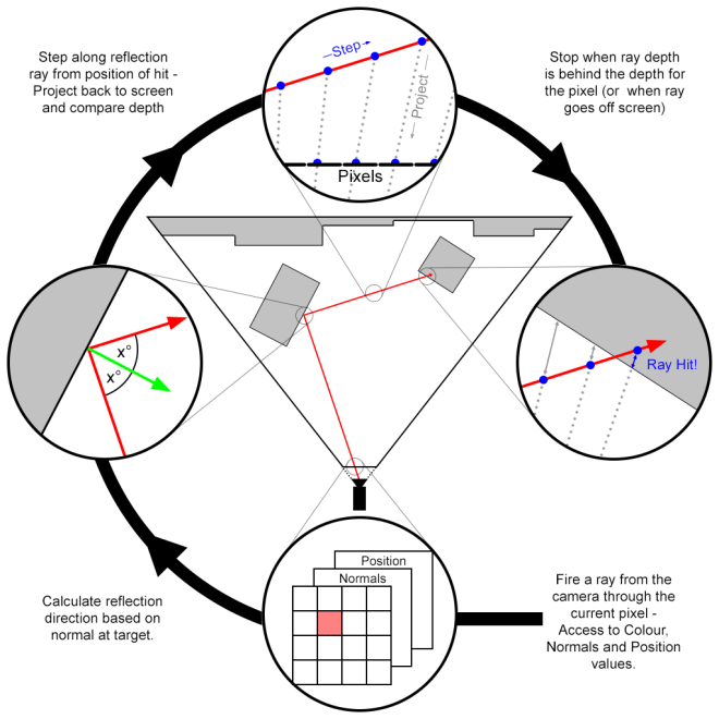
This method will result in some nice reflections, but will have a lot of banding depending on how fine the step size is. One major concern though, is that each time we step and project, we may not actually be sampling any new data as we may not be changing pixel, and equally so, we may be overstepping and skipping pixels. The oversampling makes the effect needlessly heavy, and the under-sampling costs us quality. How do we avoid this then? The solution is obvious, though not as easy to implement as one might first think: calculate the ray across the screen sampling once per pixel, then translate it back to 3D space. We’ll get to this process in a bit, but first, let’s look over the core code.
Move everything to camera space
I cannot emphasis enough how important this is and how much easier things are once it’s done. Simple Matrix transformations will move all positions to camera local space (ie, camera at 0,0,0 and pointing down the negative z axis), and rotate the normals to be in camera space.
Calculating camera ray
Calculating the ray from the camera for a pixel has been covered here before, and is quite simple to do as long as we know some basic camera settings. The focal is the distance from the camera to the “screen”, and horizontal aperture is it’s width. Some simple trigonometry tells us how to scale our vectors for each pixel. Our aspect ratio will determine how much to adjust our vertical rays (Note: this does assume the horizontal aperture is greater, we would need to adjust otherwise).
Calculate reflection ray
The reflection ray is also simple to calculate, although you may be surprised at how long it would take you to find the formula online. I’ll save you the hassle:
reflection = incident - 2 * dot(incident, normal) * normal
Why this works is again, simple trigonometry.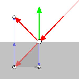
- Vectors are just directions which can all be considered to emanate from the same point.
- If we draw our incident ray (ray from the camera) from the same origin as the normal, we’ll get the faded red arrow in the diagram.
- The dot product of two vectors is the equivalent of projecting one onto the other. Projecting the incident angle onto the normal, we get the negative height of our incident ray along the normal.
- By doubling the height and multiplying it by the normal so it points in the same direction, we can deduct it (minus a negative is a plus, so we end up adding it) from our incident ray to get our output vector.
This can take a go or two to get your head around. Maths is weird.
Know our limits
Sadly, we can’t calculate all our reflections with this method. As we only have the values for any pixel facing the camera, then any ray that’s bouncing back towards the camera can only hit something we can’t see, such as the back of an object or something behind the camera. In these cases, we’ll have to find a way to fake it, so we’ll automatically ignore any reflection direction that’s coming towards the camera. The easiest way to check this is the dot product (See, it works for everything!). Seeing as we’ve moved everything to camera space, we know that anything in the positive z direction is what will fail, so by checking the dot of our camera ray with a ray pointing down the z axis (0, 0, -1), we’ll get a positive value for anything we can use, and a negative for anything going the other way. Now aren’t you glad we moved to camera space?
Trace a ray across the screen
There are a few algorithms for drawing a line across a pixel grid, the most notable of which is bresenham’s algorithm. Quick and painless, it does a great job of it, but unfortunately for our case it’s not quite what we want. While we do need to know the pixels it travels through, we also want to know exactly where in the pixel it is. Instead, we’ll use a very light system that will tell us exactly where we cross the threshold from one pixel to the next.![]()
All we need to know is how far do we travel in the x direction when we move 1 pixel in the y, and vice versa? Our reflection is already normalised (ie, has a length of one) so if we divide it into 1, we’ll find how much we need to multiply our vector by to advance one pixel in that each direction. By taking the lowest value we know which is closer, and we also know that we’ve just crossed that axis so the distance to the next threshold has just increased by the same distance. Now we can just repeat the process. Easy huh?
However, to compare the lengths we’ll need to take the absolute value so we can tell which is lower, and therefore closer, without having to worry about negative values. To keep track of whether our ray is pointing in the positive or negative direction for each axis, we’ll store a step for each axis: When we cross it’s threshold we’ll move +1 or -1 in that direction. We also keep track of what pixel we’re currently in. And last but not least, we want to start from the center of our pixel, so our starting values are only half the distance.
// Setup starting values
float3 tDelta = fabs(1.0f / refl_dir);
float3 tMax = tDelta * 0.5f; // Starting position is center of pixel
float3 average;
int pixel_x = pos.x;
int pixel_y = pos.y;
int step_x = refl_dir.x > 0 ? 1 : -1;
int step_y = refl_dir.y > 0 ? 1 : -1;
float depth_travelled, ray_depth, t2, t1 = min(tMax.x, tMax.y);
Now we can just keep repeating this method, checking which axis is closest, stepping the pixel once by it’s step value, and increasing the distance on that axis by it’s unit length until we exit the screen, or more importantly, hit our target.
do {
  if (tMax.x < tMax.y) {
    pixel_x += step_x;
    tMax.x += tDelta.x;
  }
  else {
    pixel_y += step_y;
    tMax.y += tDelta.y;
  }

  ...

  if (!src.bounds.inside(pixel_x, pixel_y))
    break;
} while (true);
Hitting our target
Now we need to know when our ray goes behind the rendered pixel position it’s currently in, and this is actually a tricky thing to figure. Multiplying a 2D pixel position by an inverted camera projection matrix won’t work as we don’t have a z value for it, and how else are we going to find out where it is? This is why we chose the above tracing method in place of bresenham’s algorithm, we can now pinpoint exactly where in the pixel our 2D line is and project a line through the point into the scene. And as we know that this 2D line is tracing exactly the path of our 3D line, we know that these two lines will intersect, giving us our 3D position.
Normally a ray-ray intersection as it’s commonly called would be a bit tricky to calculate; you need to check if they hit (an unlikely circumstance with two infinitely thin lines in 3D space) and carefully work out what value works if they do. For us, we can skip all that – We know they intersect already. Our intersection formula is as follows:
(A.x * BD.y - A.y * BD.x + B.y * BD.x - B.x * BD.y) / (AD.y * BD.x - AD.x * BD.y);
Why? I won’t go through all the math, because we may both lose our minds, but a line can be defined as a starting point (A), and a direction (AD). Every point on that line can be gotten by multiplying the direction by a distance and adding it to the point; therefore the whole line can be described as: A + AD * t, where t is the distance. We can describe both lines in this way, and we know that there is exactly one point that is shared by both, therefore:
A + AD * t = B + BD * r
As a point is made of 3 positions (x, y, z), we know they must all equal each other:
A.x + AD.x * t = B.x + BD.x * r
A.y + AD.y * t = B.y + BD.y * r
A.z + AD.z * t = B.z + BD.z * r
So we need to solve these three simultaneous equations. This is where I’ll stop explaining it, but if you’re comfortable with algebra, feel free to sit down and simply write it out, it’s fairly straightforward, and you’ll end up with the equation posted above by using two of the axis’.
Now, although we know they intersect, there are edge cases where using the x and y values will actually cause an incorrect result, and we’ll get a negative value. To get around this, we can use the x and z, or y and z instead. This is a simple loop for as long as we have a negative result. Now we know the distance from our starting position to the intersection, and calculate the intersection z-depth. As we’re in camera space, we only need to compare the z values against each other and can avoid expensive length() checks (It was really worth moving to camera space for this).
To get a more accurate result, we keep the entry point to our current pixel from the last loop and calculate the exit point, then average them to get a position as close to central on the pixel as possible for emitting our ray through. The difference is minor, but why not be accurate?
// Center of ray through pixel
t2 = min(tMax.x, tMax.y);
average = refl_dir * (t1 + t2) * 0.5f;
t1 = t2;

// Calculating the eye vector for the current pixel
float u = (pos.x + 0.5f + average.x) / width - 0.5f;
float v = (pos.y + 0.5f + average.y) / height - 0.5f;
cam_ray_dir = float3(u, v * aspect, -ratio);

// Compare ray depth to world depth and end if ray has gone behind image
depth_travelled = intersection(starting_world_pos, float3(0,0,0), refl_dir, cam_ray_dir);
ray_depth = starting_world_pos.z + depth_travelled * refl_dir.z;
if (!src.bounds.inside(pixel_x, pixel_y) || ray_depth <= world_pos(pixel_x, pixel_y, 2))
  break;
We can actually now move the if condition into the while condition for our loop, saving another expensive conditional branch on our kernel.
Finally, setting the value
Having at last found the light at the end of our ray-nbow (I’m so sorry), we have one of three results, and can choose to handle each case however we’d like:
- The ray is outside the image: Without any other data to use, we can either sample from a hdri spherical mapping, or just return a blank value.
- The ray is hidden behind another object. We can tell if this is the case by checking if the distance we’re behind the current pixel is greater than we could have moved in one ray step (or alternatively, give the user a threshold value for more control). This is our worst case scenario, as it means we are missing what will generally be a very prominent reflection. It can also be an issue when the ray tries to pass behind an object, and should continue on, eg, a lamppost. We could counter that last issue by tweaking the loop code to continue irregardless and seeing if we hit anything later, but this can introduce it’s own problems. Like with the first option, we can return a hdri mapping or a blank value.
- The ray has hit the image: We can choose the colour value at the pixel co-ordinates we’ve ended up on. Because we’ve also got an exact position within the pixel, we could use a bilinear filter for smoother reflections, but this can cause issues with the borders of where our rays hit and are hidden, stretching out the result into a rather ugly mess.
I’ve been playing around with taking this a step further, and have successfully made a cheap way to bounce the rays to keep reflections of reflections, as well as tracking the distance each ray has travelled to control the falloff of the reflection, but I’d better save something for when I actually get around to uploading the finished tool!
And there we have it. A very inexpensive way of calculating screen space reflections, with minimal conditional branching. I hope this has been of use to you, and watch this space for the final product.

Hi thanks for postinng this
LikeLike